dinsdag 27 maart 2018
Universal brake generator for DCC & MM
I have been working on a universal brake module voor DCC & Motorola, to be used with the simple booster-hub we use at our club:
maandag 20 mei 2013
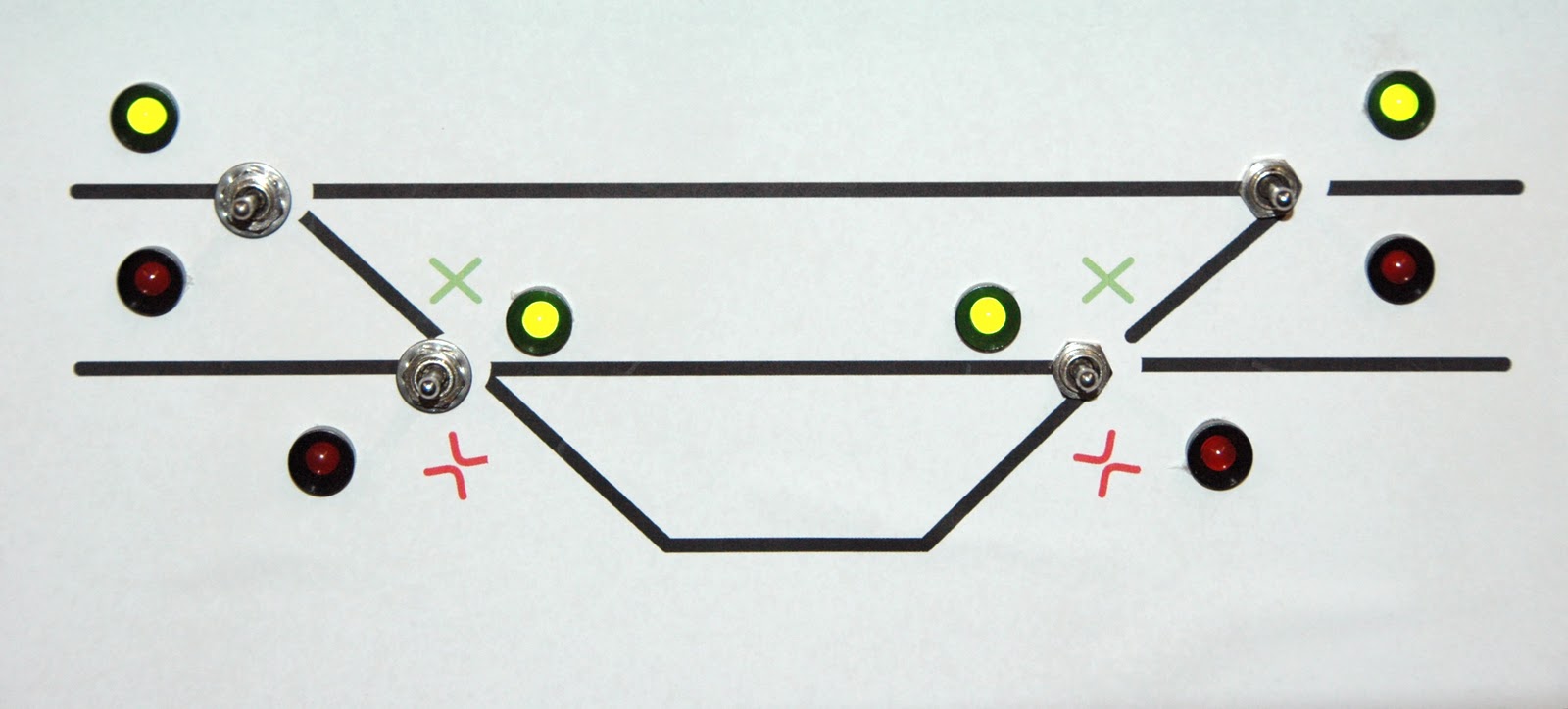
2-wire signals
For my children I bought some Märklin rails and trains. In the 'Märklin My World' series there are some nice cheap electronics, like turnout controls, signals and signal controls.
One thing I noticed, however, is the lack of Dutch signals. Since Märklin is German, all of the available signals are also German.
Dutch signals are very simple: they have 3 lights: green, yellow, and red. There are some signals available, from small-scale manufacturers, and they are mostly wired using leds and a common wire. The Märklin signals have 2 lights (as German signals apparently have), and are wired using 2 wires: the leds are connected back-to-back, and they are lit using either a positive or a negative voltage.
I bought a signal controller and one signal and checked this. So to use other signals, I needed a circuit to convert the 2-wire voltage to a 3-wire connection (the yellow light is not used in my setup at the moment).
The setup in the 'My World' package includes a basic signal setup: the rails before the signal is isolated, and connected to the signal control box, and only connected to the controller when the signal light is green. Similar to an analogue set-up, although the controller in the "My World" package is digital. So there are only 2 states in this setup: green and red.
I made this circuit to convert the 2-wire connection to a 3-wire signal:
 The diodes are there to protect the Leds, I used simple 1N4148 types. The resistors are 1K, although the one in the middle is part of the signal (the grey circle), so it depends on the voltage and leds used.
I tested this on my breadboard and it worked fine, now I need to buy some signals and put it all together. I am thinking of expanding this circuit to include the yellow light, but then I need some logic to tie them together: the yellow light is lit depending on the next signal: if it has an input that says 'clear' (green), but the next sign is 'stop' (red), then it should be yellow instead of green. There are other functions, but I won't go that far.
One thing I noticed, however, is the lack of Dutch signals. Since Märklin is German, all of the available signals are also German.
Dutch signals are very simple: they have 3 lights: green, yellow, and red. There are some signals available, from small-scale manufacturers, and they are mostly wired using leds and a common wire. The Märklin signals have 2 lights (as German signals apparently have), and are wired using 2 wires: the leds are connected back-to-back, and they are lit using either a positive or a negative voltage.
I bought a signal controller and one signal and checked this. So to use other signals, I needed a circuit to convert the 2-wire voltage to a 3-wire connection (the yellow light is not used in my setup at the moment).
The setup in the 'My World' package includes a basic signal setup: the rails before the signal is isolated, and connected to the signal control box, and only connected to the controller when the signal light is green. Similar to an analogue set-up, although the controller in the "My World" package is digital. So there are only 2 states in this setup: green and red.
I made this circuit to convert the 2-wire connection to a 3-wire signal:

I tested this on my breadboard and it worked fine, now I need to buy some signals and put it all together. I am thinking of expanding this circuit to include the yellow light, but then I need some logic to tie them together: the yellow light is lit depending on the next signal: if it has an input that says 'clear' (green), but the next sign is 'stop' (red), then it should be yellow instead of green. There are other functions, but I won't go that far.
donderdag 10 januari 2013
Märklin 6027
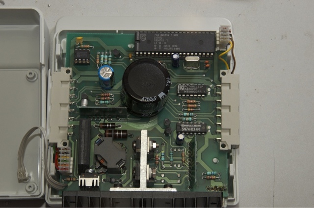
I've been busy trying to repair a Märklin base station for a friend; strange enough, the device is meant to be used for 2-rail DC systems instead of Märklin's own 3-rail AC system.
It stems from the early area of digital railroading, when Märklin to collaborate with Lenz and Arnold to market a universal system.
The device is quite sophisticated: a philips microcontroller, and some special darlington transistors for the heavy lifting (the builtin booster).
The device I repaired seemed to be an early version; I came across a later model on eBay, and they differed in quite a few aspects.
The old model had only the Philips Microprocessor, while the newer version had an extra EPROM.
The versions printed on the processors were also quite interestin: the old one said 'LZ v1.0', but the new one said 'LZV 4.1 (c) LENZ'. And 'LZV' is the type of Lenz's own base stations. So I wonder about the innards of the software, and whether it works with other DCC equipment. When I manage to get some other modules to connect it with, I will do some more experiments.
maandag 19 september 2011
Digital control panels?

Well, for testing and 'local control' these panels turned out to be indispensable, so I have built a few of them, spread out over each part of the layout.
This one I built with the classical toggle switches (on-off-on or sp-dt), and LEDs to show the current position. This is a simple station with one side-track, but with crossover turnouts, so the trains can change to either of the two tracks.

For this I used pushbutton switches with built-in LEDs, this way I only needed one hole for both switch and indicator. The 5 LEDs next to the turnouts are used to denote the position of the signals.
The two switches on the bottom were used to control the light on the station and platform.
maandag 22 augustus 2011
ESU Lokpilot DCC V4.0
For some obscure reason, ESU has decided to change the structure of their LokPilot decoders radically, so that it is impossible to program them in any 'upwards-compatible' way. They are using 'indexed' CV's, which means you first program a CV to get to the bank of CVs you need, and the program these. The range of CVs leads to the 300-500 range, so doing this by hand is neigh impossible. IMHO this is a a bit over the top, there was plenty of room in the lower CVs to spare (CV 133-245 are still unused).
I have been watching JMRI's decoderpro pages to see if anyone had been working on a template on this, and I found the following:
- The LokSound V4.0 was included in the 2.12 release
- There was a 'work in progress' file for a LokPilot DCC v4.0 decoder
Using this, I got the decoder working, but there were still issues.
Abonneren op:
Reacties (Atom)